The breadboard or solderless breadboard is the most popular tool used for prototyping (building temporary electronic circuits and testing them before the final version is permanently designed) without any need for soldering.
In this article we will cover the basics you need to know about the breadboard, types of breadboards and which components are compatible with the breadboard.
Why do we call it a breadboard?
You may ask “what does a breadboard have to do with electronics?” And if your imagination pictures a fresh loaf on a piece of wood, then you are not far from guessing where the name comes from. The name “breadboard” goes way back to the days when people would literally use a piece of wood on which they sliced bread in order to construct electronic circuits. They used nails and wires to connect up the components. Nowadays, the new generation of “breadboard” is made from a rectangular piece of plastic, but we still refer to them by the name “breadboard.”
Types of breadboard
Breadboards come in various brands and sizes to suit the requirements of the electronic circuit. Nevertheless, all breadboards share the same fundamentals and ideas. Here are some types of a standard breadboard:
- Full-size
- Half-size
- Mini
Moreover, there are different colors of breadboards (white, blue, red, green, yellow, transparent).
What is the breadboard terminology?
Almost all modern (full-size and half-size) breadboards have numerous holes, letters, numbers, and blue and red lines that give the breadboard its standard appearance. Here is the terminology you must know:
Letters
Printed at the top and bottom of the breadboard are letters from “A” to “J” running horizontally and dividing the holes evenly into vertical lines.
Numbers
To identify horizontal rows, numbers from 1 to 30 are printed on left and right edges on half-size breadboards, and to 60 or 63 on full-size breadboards. Some breadboards use skip-counting in fives, but it doesn’t change the main concept of rows numbering on breadboards.
Horizontal Row
The rows or “terminal strips” are where you are supposed to connect the electronic components. Rows are identified by numbers, and each row contains five holes on each side (left and right) separated by a middle divider. All five holes in the same row are electrically connected, but they must be on the same side.
Vertical Bus
This consists of two vertical columns that are commonly known as “power rails.” Each breadboard contains two power rails located at the ends of both sides on the breadboard. The purpose of the power rails is to connect the circuit to an external power supply. One column is to connect the circuit with the positive voltage (+) and the other column is to connect the circuit with the ground (-).
Central gutter
A middle divider or “ravine” runs vertically and divides the breadboard symmetrically into left and right sides. As we mentioned earlier, the halves of the breadboard are electrically isolated from each other by the middle divider.
Which electronics components can be used on breadboards?
Almost all components that have leads and are known as THT (through the hole technology) components can be used on breadboards. Since there is no need for soldering, we can connect the components simply by pushing the leads into the hole’s metal clips.
How to build a circuit using a breadboard
Now you have the basic knowledge to start building electronic circuits. The feeling of seeing your first circuit working is amazing!
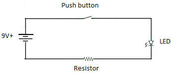
To build an electronic or electric circuit, it is highly recommended to follow a circuit schematic or diagram. The circuit schematic is a pictorial representation of the circuit connections and uses a special symbol for each component.
We will explain the circuit schematic in a separate tutorial, but we are going to use a simple example to learn how to build a circuit using the breadboard.
So, let’s start

Given the schematic above, the circuit is intended to light the LED whenever the push button is pressed.
Steps:
-
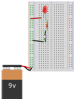
Place the push button anywhere on the breadboard (do not put both leads on the same row). Connect it from one side to the ground bus (-) a via jumper wire.
-
Connect the other side of the push button directly to the resistor. “Directly” means there’s no need for jumper wire (remember that every five holes in the same row are connected by default).
-
Connect the negative lead (cathode) of the LED directly to the resistor.
-
Connect the positive lead (anode) of the LED to the positive bus (+) via a jumper wire.
-
Finally, connect the ground wire (-) from the power supply to the ground bus (-) on the breadboard, then connect the positive wire (+) from the power supply to the positive bus on the breadboard (+).
-
Press the push button to test the circuit. The LED should light up. ENJOY your first circuit.
 |
||||
|---|---|---|---|---|
If the circuit doesn’t work, check the connections carefully and follow the steps from the beginning.
In our Electronics Experiments Kit we use the breadboard as the main component on which we carry out the experiments. Read more about our educational kits on our website and start doing cool projects with the breadboard.
Want to learn more? Check the full lecture here!
We hope you enjoyed this article. If you liked it, share it with your friends and follow our fan page on Facebook to stay up-to-date with our latest news. See other topics on our website to learn more about electronics through our online tutorials.


