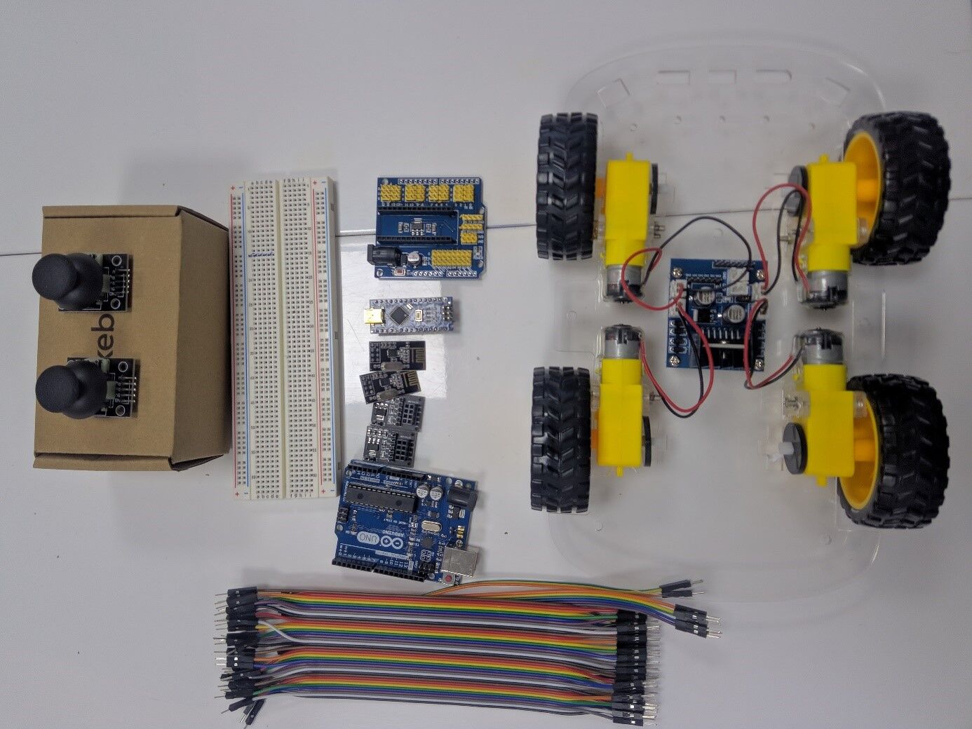
In this topic, I would like to show you how to make a remote control car with NRF24L01 PA LNA module. Of course, there are several other typed of radio modules, such as 433MHz, HC12, HC05, and LoRa, that can be chosen depending on the payload you want. However, in my opinion, NRF24L01 module is quite good because the price is affordable and can make long-distance communication with fast data transmission. When viewed from the datasheet, this module can communicate up to 1 km in open space and without obstacles. Besides modules, antennas can also affect the radius of range to communicate.
LET'S MAKE IT!

Equipment you will need:
- Transmitter: Nrf24l01, Nrf24l01 holder, Arduino Nano, Arduino Nano shield, jumper wires(MF, FF, MM), 2 joysticks, a small card box.
- Receiver: Nrf24l01, nrf24l01 holder Arduino Uno/Nano, battery cell, l298N driver motor, jumper wire(MF, FF, MM), 4Dc motors, 2 or 1 servo motors for the gimbal, Arduino Nano shield( if Arduino Nano is used), a breadboard.
Circuit diagram:
- 1)TX: ,2) RX:
Code:
Transmitter code:
#include <SPI.h>
#include <nRF24L01.h>
#include <RF24.h>
// Define the digital inputs
#define jB1 1  // Joystick button 1

RF24 radio(7, 10);   // nRF24L01 (CE, CSN)
const byte address[6] = "00001"; // Address
// Max size of this struct is 32 bytes - NRF24L01 buffer limit
struct Data_Package {
    byte j1PotX;
    byte j1PotY;
    byte jPotX;
    byte jPotY;

    };
    Data_Package data; //Create a variable with the above structure
    void setup() {
      Serial.begin(9600);
      // Define the radio communication
      radio.begin();
      radio.openWritingPipe(address);
      radio.setAutoAck(false);
      radio.setDataRate(RF24_250KBPS);
      radio.setPALevel(RF24_PA_LOW);

// Activate the Arduino internal pull-up resistors

// Set initial default values
      data.j1PotX = 127; // Values from 0 to 255. When Joystick is in resting position, the value is in the middle, or 127. We actually map the pot value from 0 to 1023 to 0 to 255 because that's one BYTE value
      data.j1PotY = 127;
      data.jPotX = 127;
      data.jPotY = 127;
}
void loop() {
      // Read all analog inputs and map them to one Byte value
      data.j1PotX = map(analogRead(A3), 0, 1023, 0, 255); // Convert the analog read value from 0 to 1023 into a BYTE value from 0 to 255
      data.j1PotY = map(analogRead(A2), 0, 1023, 0, 255);
      data.jPotX = map(analogRead(A1), 0, 1023, 0, 255);
      data.jPotY = map(analogRead(A0), 0, 1023, 0, 255);

// Read all digital inputs
//data.j1Button = digitalRead(jB1);
Serial.println(analogRead(A2));
 // Send the whole data from the structure to the receiver
radio.write(&data, sizeof(Data_Package));
    }
Receiver code:
#include <SPI.h>
#include <nRF24L01.h>
#include <RF24.h>
#include <Servo.h>
#define enA 4  // Note: Pin 9 in previous video ( pin 10 is used for the SPI communication of the NRF24L01)
#define in1 5
#define in2 6
#define enB 11   // Note:  Pin 10 in previous video
#define in3 8
#define in4 9
RF24 radio(7, 10);   // nRF24L01 (CE, CSN)
const byte address[6] = "00001";
unsigned long lastReceiveTime = 0;
unsigned long currentTime = 0;
Servo ser1, ser2;
int pote0,pote1,pote2,pote3;
// Max size of this struct is 32 bytes
struct Data_Package {
     byte j1PotX;
     byte j1PotY;
     byte jPotX;
     byte jPotY;
    };

Data_Package data; //Create a variable with the above structure

int  xAxis, yAxis;
int motorSpeedA = 0;
int motorSpeedB = 0;
void setup() {
     ser1.attach(2);
     ser1.write(90);
     ser2.attach(3);
     ser2.write(90);
      pinMode(enA, OUTPUT);
      pinMode(enB, OUTPUT);
      pinMode(in1, OUTPUT);
      pinMode(in2, OUTPUT);
      pinMode(in3, OUTPUT);
      pinMode(in4, OUTPUT);
      Serial.begin(9600);
      radio.begin();
      radio.openReadingPipe(0, address);
      radio.setAutoAck(false);
      radio.setDataRate(RF24_250KBPS);
      radio.setPALevel(RF24_PA_LOW);
      radio.startListening(); //  Set the module as receiver
      resetData();
}
void loop() {
 // Check whether we keep receving data, or we have a connection between the two modules
      currentTime = millis();
 if ( currentTime - lastReceiveTime > 1000 ) { // If current time is more then 1 second since we have recived the last data, that means we have lost connection
        resetData(); // If connection is lost, reset the data. It prevents unwanted behavior, for example if a drone jas a throttle up, if we lose connection it can keep flying away if we dont reset the function
      }
 // Check whether there is data to be received
 if (radio.available()) {
        radio.read(&data, sizeof(Data_Package)); // Read the whole data and store it into the 'data' structure
 lastReceiveTime = millis(); // At this moment we have received the data
      }

 pote0= map(data.jPotX,0,255,0,179),ser1.write(pote0);
 pote1= map(data.jPotY,0,255,0,179),ser2.write(pote1);

 xAxis = data.j1PotY;
  yAxis = data.j1PotX;

     // Y-axis used for forward and backward control
  if (yAxis < 110) {
     // Set Motor A backward
     digitalWrite(in1, HIGH);
     digitalWrite(in2, LOW);
     // Set Motor B backward
      digitalWrite(in3, HIGH);
      digitalWrite(in4, LOW);
     // Convert the declining Y-axis readings for going backward from 110 to 0 into 0 to 255 value for the PWM signal for increasing the motor speed
     motorSpeedA = map(yAxis, 110, 0, 0, 255);
     motorSpeedB = map(yAxis, 110, 0, 0, 255);
     Serial.print(motorSpeedA);
     Serial.print("  ");
     Serial.println(yAxis);
      }
 else if (yAxis > 140) {
    // Set Motor A forward
    digitalWrite(in1, LOW);
    digitalWrite(in2, HIGH);
     // Set Motor B forward
     digitalWrite(in3, LOW);
     digitalWrite(in4, HIGH);
      // Convert the increasing Y-axis readings for going forward from 140 to 255 into 0 to 255 value for the PWM signal for increasing the motor speed
        motorSpeedA = map(yAxis, 140, 255, 0, 255);
        motorSpeedB = map(yAxis, 140, 255, 0, 255);
      }
     // If joystick stays in middle the motors are not moving
else {
     motorSpeedA = 0;
     motorSpeedB = 0;
      }
     // X-axis used for left and right control
 if (xAxis < 110) {
     // Convert the declining X-axis readings from 140 to 255 into increasing 0 to 255 value
        int xMapped = map(xAxis, 110, 0, 0, 255);
     // Move to left - decrease left motor speed, increase right motor speed
    motorSpeedA = motorSpeedA - xMapped;
    motorSpeedB = motorSpeedB + xMapped;
     // Confine the range from 0 to 255
if (motorSpeedA < 0) {
     motorSpeedA = 0;
        }
if (motorSpeedB > 255) {
      motorSpeedB = 255;
        }
      }
if (xAxis > 140) {
     // Convert the increasing X-axis readings from 110 to 0 into 0 to 255 value
      int xMapped = map(xAxis, 140, 255, 0, 255);
     // Move right - decrease right motor speed, increase left motor speed
    motorSpeedA = motorSpeedA + xMapped;
        motorSpeedB = motorSpeedB - xMapped;
      // Confine the range from 0 to 255
 if (motorSpeedA > 255) {
         motorSpeedA = 255;
        }
 if (motorSpeedB < 0) {
     motorSpeedB = 0;
        }
      }
      // Prevent buzzing at low speeds (Adjust according to your motors. My motors couldn't start moving if PWM value was below value of 70)
 if (motorSpeedA < 70) {
     motorSpeedA = 0;
      }
if (motorSpeedB < 70) {
      motorSpeedB = 0;
      }
 analogWrite(enA, motorSpeedA); // Send PWM signal to motor A
 analogWrite(enB, motorSpeedB); // Send PWM signal to motor B
    }
void resetData() {
     // Reset the values when there is no radio connection - Set initial default values
      data.j1PotX = 127;
      data.j1PotY = 127;
      data.jPotX = 127;
      data.jPotY = 127;

}Conclusion:
This robot can be used as an environmental monitoring robot, a kind of a terrestrial robot (UGV) similar to a small car. Its main purpose is to explore inaccessible places to collect data. Terrestrial robots make a huge impact on agricultural, transportation, and surveillance sector.


